Hello,
I'm having more problems with my custom bq24610 board. The circuit is based on the example in the bq24610 datasheet, and has the following settings:
ISET1 (Fast Charge): 100k/20k = 0.550V (2.75A)
ISET2 (Precharge): 100k/56.2k = 1.18V (1.18A)
ACSET (Input Current): 100k/34.8k = 0.852V (4.26A)
Battery Voltage: 301k/100k (VBAT = 2.1V x (1 + 301k / 100k) = 8.42V)
While running the bq24610 on AC_PWR = 11.3V with a battery simulator set to 6.5V, I expect to see a charge current of 2.75A, but I am only getting 0.75A. I measured the following:
VREF = 3.32V (expected 3.3V)
ISET1 = 0.554V (expected 0.550V)
ISET2 = 1.193V (expected 1.18V)
ACSET = 0.857V (expected 0.852V)
VBATT = 6.5V (expected 6.5V)
VFB = 1.621V (expected 1.621V = 6.5V * 100k / (100k + 301k))
REGN = 6V (expected 6V)
ICHG = 0.75A (measured using ammeter with 30 milliohm shunt resistance)
I captured the following waveforms: HIDRV, LODRV, BTST, and PH (see images below). HIDRV seems reasonable to me, but I expect LODRV to drive when HIDRV is off, but it's only on for the first portion of its window. When I try this same test using the bq24610EVM board LODRV is driving when HIDRV is off and I get the correct charge current.
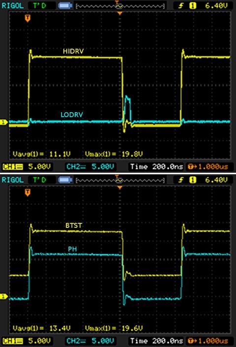
On the 'scope images, both traces share the same zero positions (up two divisions from the bottom of the display). I believe the overshoot is mostly due to inductance in the ground leads of my probes.
Varying the battery voltage doesn't change the 0.75A charge current much until it stops charging all together when I get close to the 8.4V maximum battery voltage. Any help or thoughts would be most appreciated.
Thank you!
-Ross